RCWA/FDTD Convergence Analysis Report
Generated on 2026-05-07 from local outputs/ benchmark artifacts.
This page turns the Python-level benchmark outputs into a publication-style report. The source JSON and plots stay in outputs/ for local iteration, while selected figures and tables are promoted to docs/public/reports/convergence/ so the same evidence can be served by GitHub Pages.
How to read this report
- If you are evaluating COMPASS as a user, read the executive summary, the convergence tables, and the interpretation section. Those parts explain which numbers are ready to trust and which ones are still visual proxies.
- If you are maintaining solver code, use the validation ladder and regeneration commands as an internal checklist. The goal is to keep 1D physics, 2D trench alignment, and full-pixel visual checks from being mixed into one ambiguous test.
Executive summary
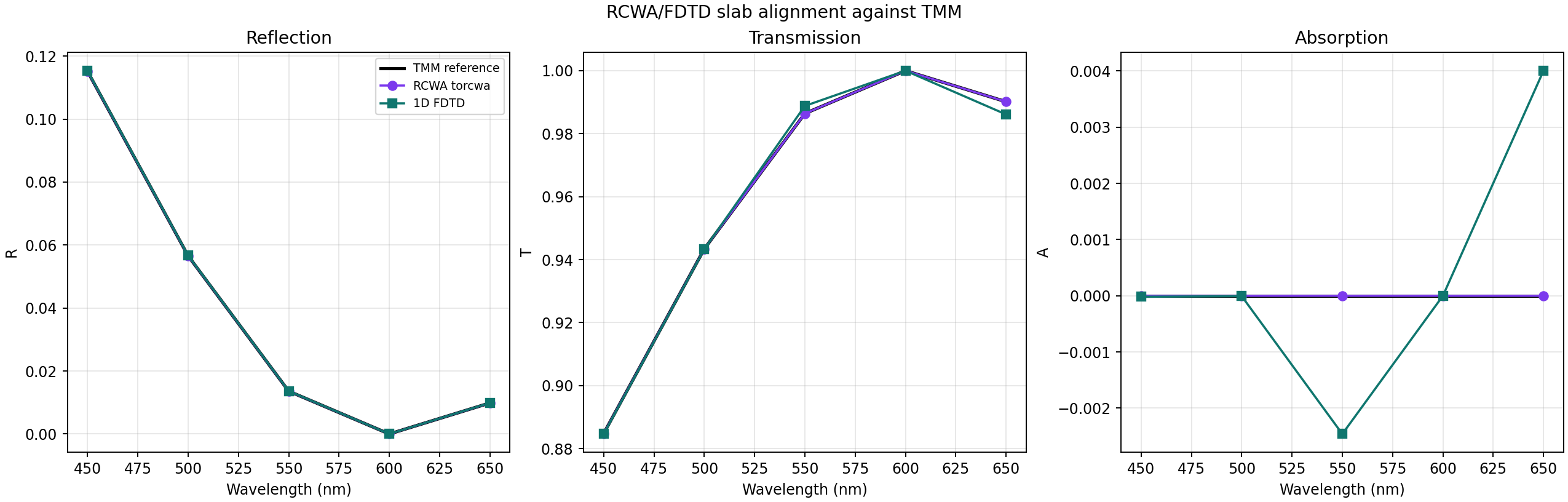
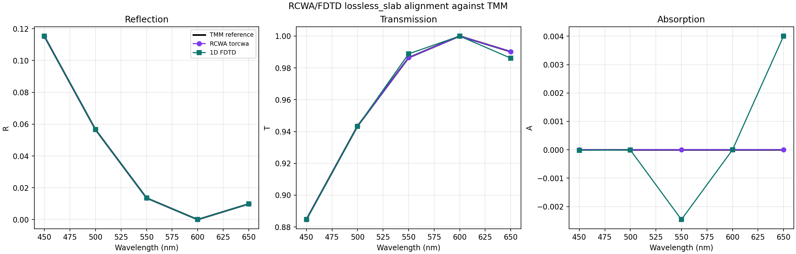
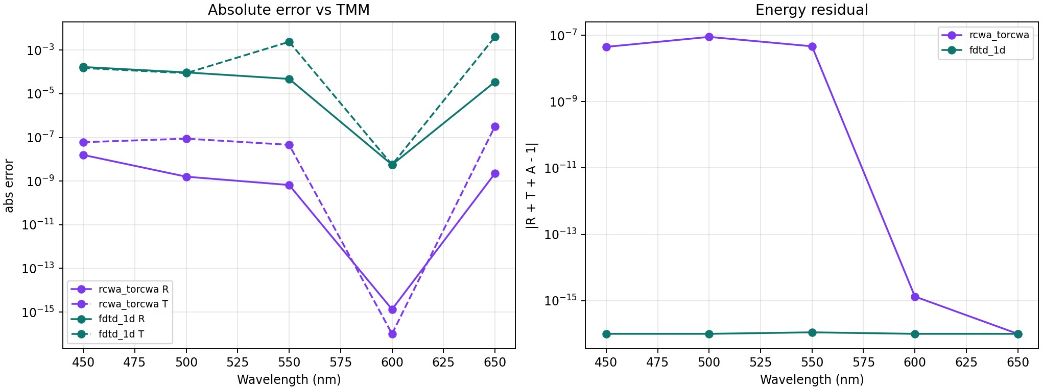
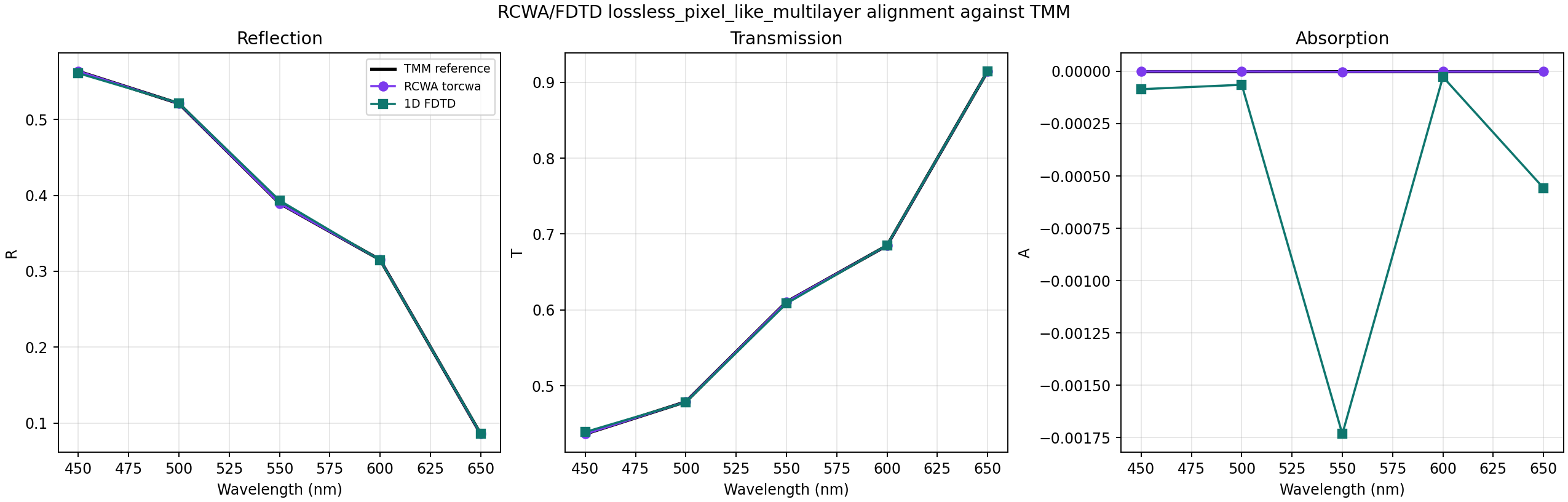
- The 1D ladder is aligned: torcwa RCWA matches TMM at near numerical precision, and the 1D FDTD implementation is within the sub-percent target on the lossy pixel-like multilayer.
- The 2D periodic trench benchmark is aligned for FDTI and BDTI at the current coarse settings, with maximum R/T/A differences below roughly 3 percentage points.
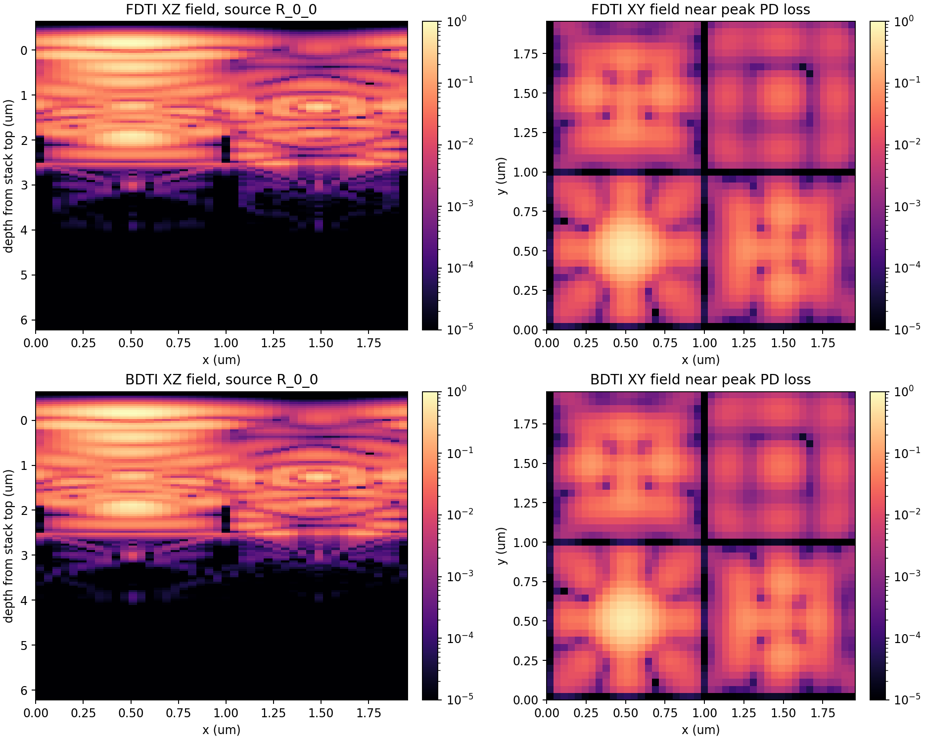
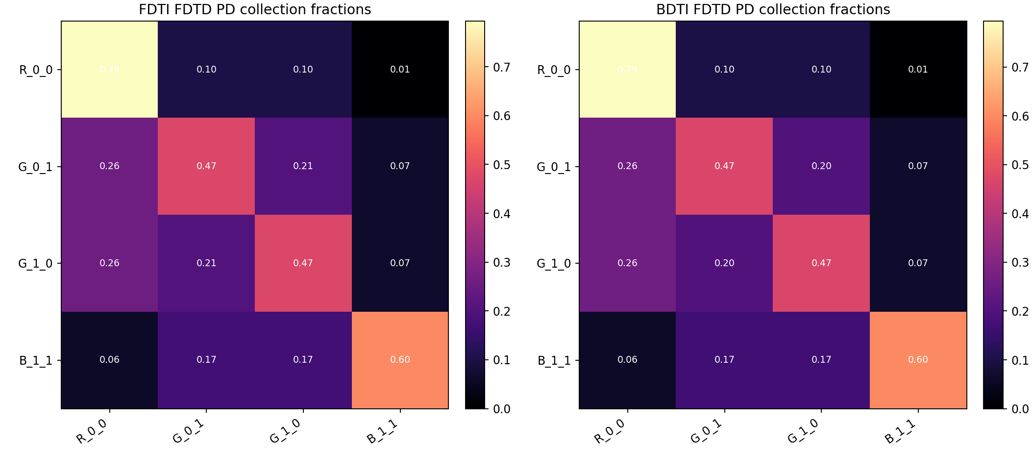
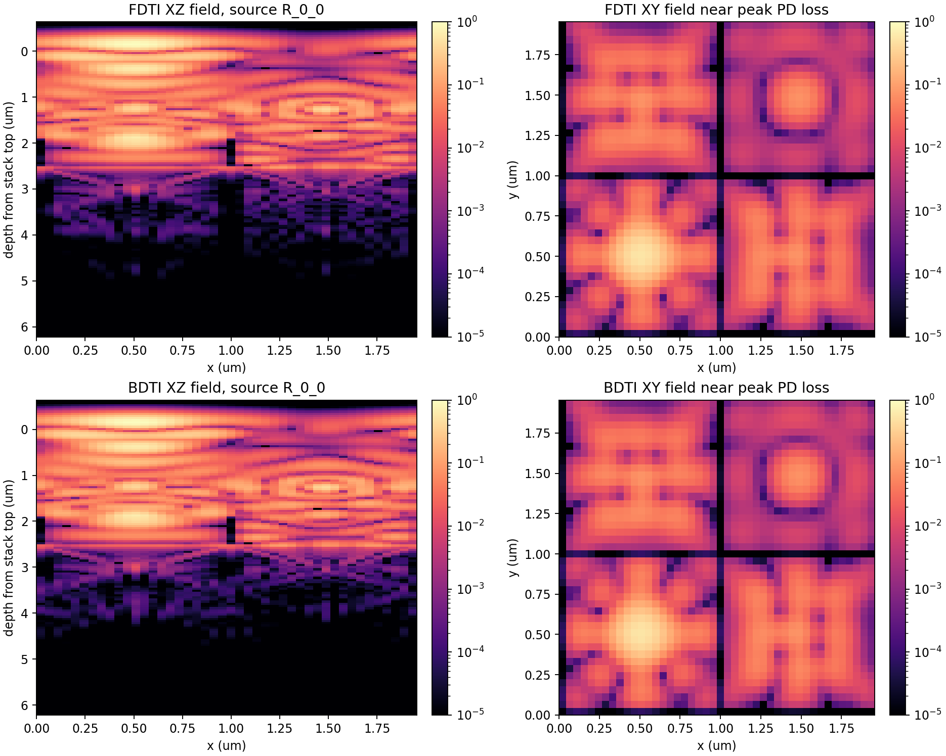
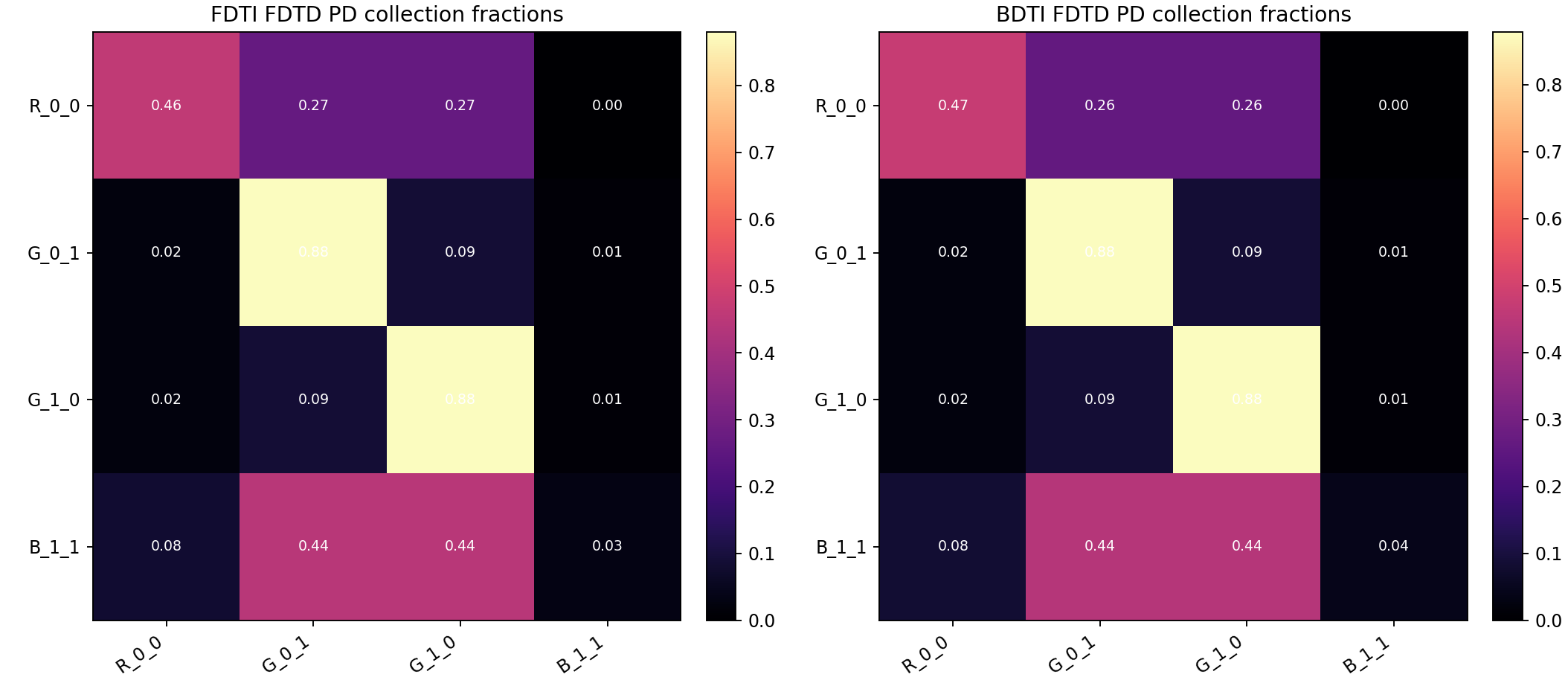
- The full 2x2 pixel scalar FDTD runs are visual convergence tests. The 44x44x118, 3500-step run is the current stable comparison point. The 64x64x170 and 128x128x340 runs need longer physical runtime before their crosstalk fractions should be treated as final.
Read the high-resolution FDTD rows carefully
A fixed --fdtd-steps value is not equivalent across grids. Finer grids use a smaller time step, so they cover less physical time unless the step count is scaled. Compare the reported c*time and energy-tail values, not only the grid dimensions.
Internal validation protocol
The report is intentionally split into three rungs. Do not use the full pixel proxy to debug a normalization issue that should have failed in the 1D ladder.
- 1D alignment validates material loss, source normalization, monitor math, and energy accounting against an analytical TMM reference.
- 2D periodic trench alignment validates FDTI/BDTI geometry direction, boundary conditions, and R/T/A consistency on a shared periodic structure.
- Full-pixel visual convergence validates realistic stack construction, photodiode windows, and crosstalk proxies. Treat it as a visual and diagnostic benchmark until the energy tail is below the target threshold.
Regeneration commands
uv run python scripts\rcwa_fdtd_alignment.py --structure lossy-multilayer --outdir outputs\rcwa_fdtd_alignment_lossy
uv run python scripts\rcwa_fdtd_trench_benchmark.py --convergence --outdir outputs\rcwa_fdtd_trench_benchmark
uv run python scripts\rcwa_fdtd_pixel_benchmark.py --fdtd-steps 3500 --outdir outputs\rcwa_fdtd_pixel_benchmark_steps3500
uv run python scripts\generate_convergence_report.py
High-resolution pixel checks can be regenerated with:
uv run python scripts\rcwa_fdtd_pixel_benchmark.py --nx 64 --ny 64 --nz 170 --fdtd-steps 5200 --outdir outputs\rcwa_fdtd_pixel_benchmark_64x64x170_steps5200
uv run python scripts\rcwa_fdtd_pixel_benchmark.py --nx 128 --ny 128 --nz 340 --source-set single --fdtd-steps 10400 --outdir outputs\rcwa_fdtd_pixel_benchmark_128x128x340_single_steps10400
uv run python scripts\generate_convergence_report.py
1D solver-alignment ladder
| Structure | RCWA ok | FDTD ok | max |Rrcwa-Rtmm| | max |Rfdtd-Rtmm| | max |Tfdtd-Ttmm| |
|---|---|---|---|---|---|
| lossless_slab | yes | yes | 1.57e-08 | 0.0002 | 0.004 |
| lossless_pixel_like_multilayer | yes | yes | 1.14e-06 | 0.0039 | 0.0026 |
| lossy_pixel_like_multilayer | yes | yes | 7.26e-07 | 0.0026 | 0.0011 |
1D slab: TMM vs torcwa RCWA vs 1D FDTD
01 Slab Spectrum Alignment
01 Spectrum Alignment
02 Alignment Errors
1D lossless multilayer: TMM vs torcwa RCWA vs 1D FDTD
01 Spectrum Alignment
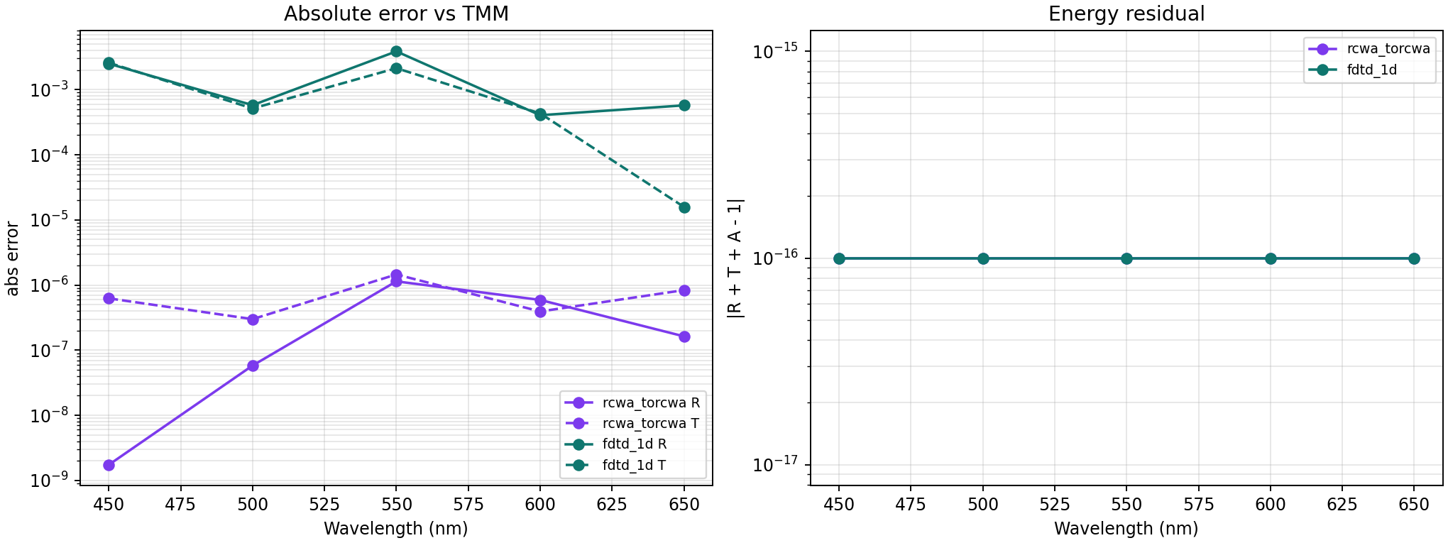
02 Alignment Errors
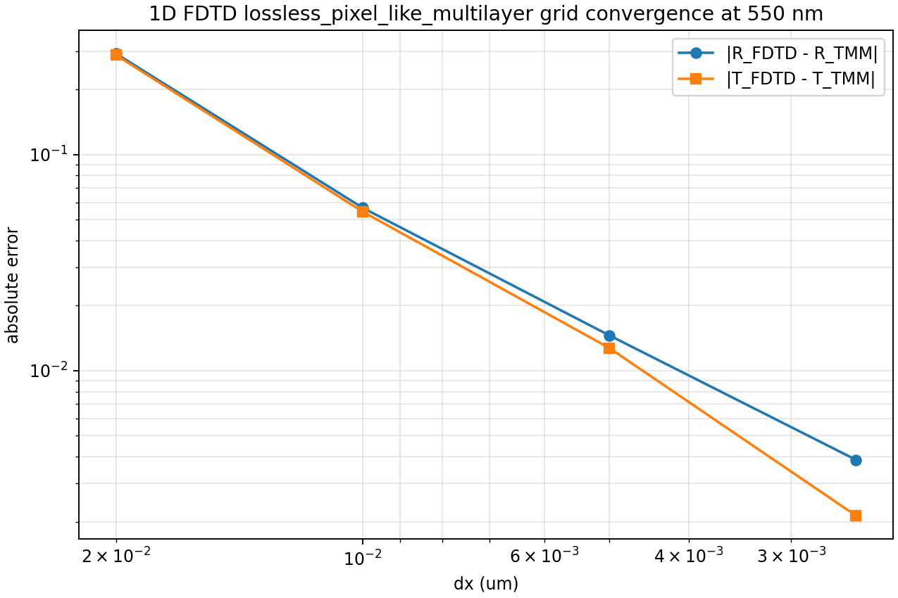
03 Fdtd Grid Convergence
1D lossy pixel-like multilayer: TMM vs torcwa RCWA vs 1D FDTD
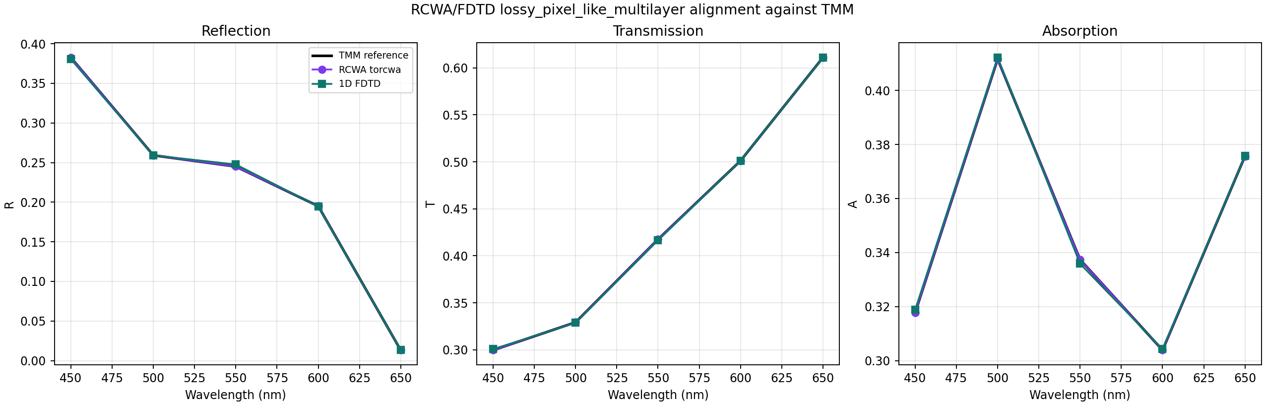
01 Spectrum Alignment
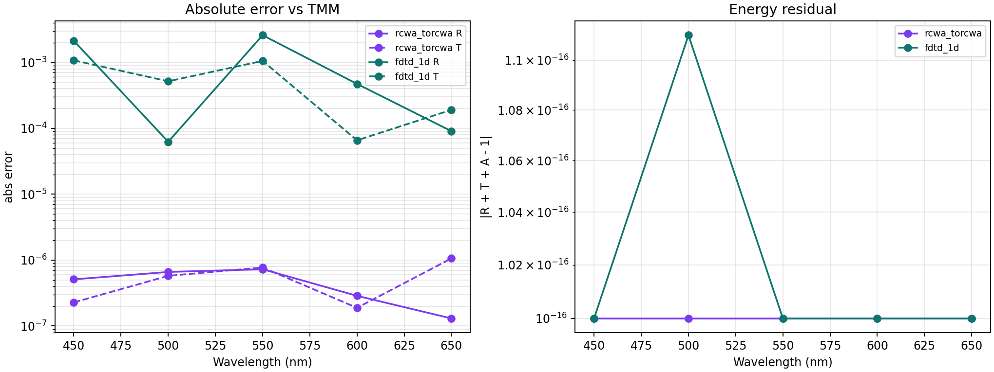
02 Alignment Errors
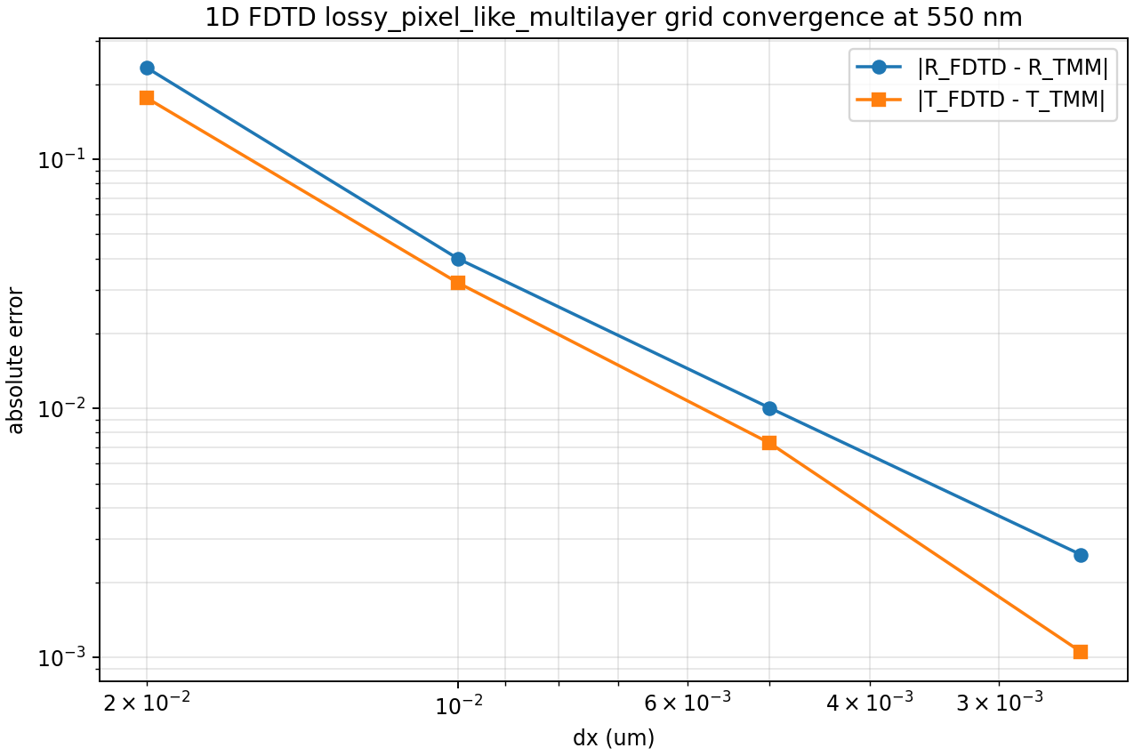
03 Fdtd Grid Convergence
2D FDTI/BDTI periodic trench
This benchmark uses one shared periodic trench geometry for both solvers. It is the first rung where FDTI and BDTI directionality matters.
| Mode | RCWA order | FDTD dx um | max |dR| | max |dT| | max |dA| | field leakage | aligned |
|---|---|---|---|---|---|---|---|
| FDTI | 3 | 0.015 | 0.0266 | 0.027 | 0.0278 | 0.1305 | yes |
| BDTI | 3 | 0.015 | 0.0183 | 0.0088 | 0.019 | 0.096 | yes |
2D periodic FDTI/BDTI trench: torcwa RCWA vs 2D TE FDTD
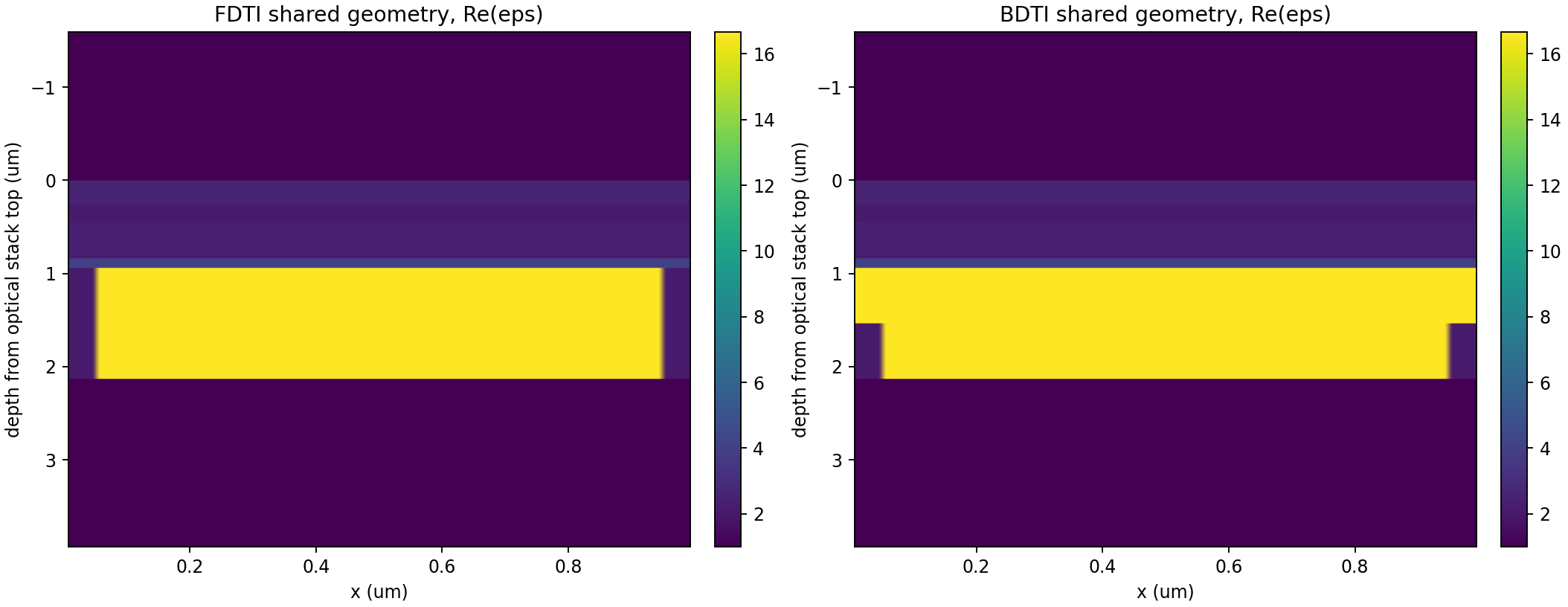
01 Shared Geometry
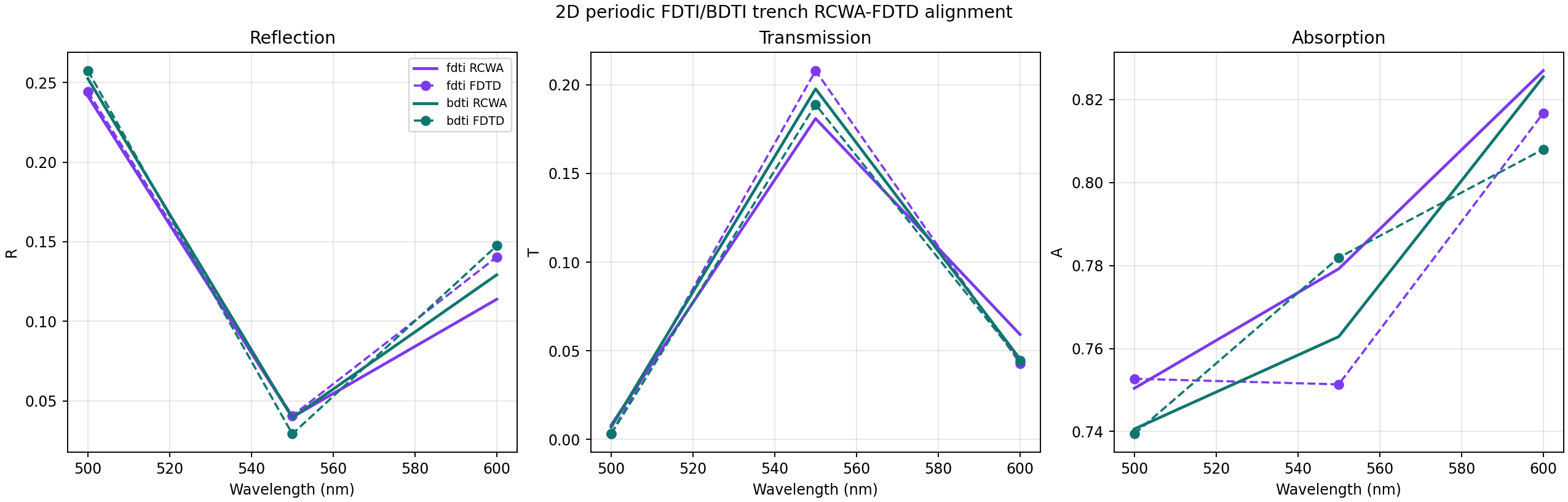
02 Spectrum Alignment
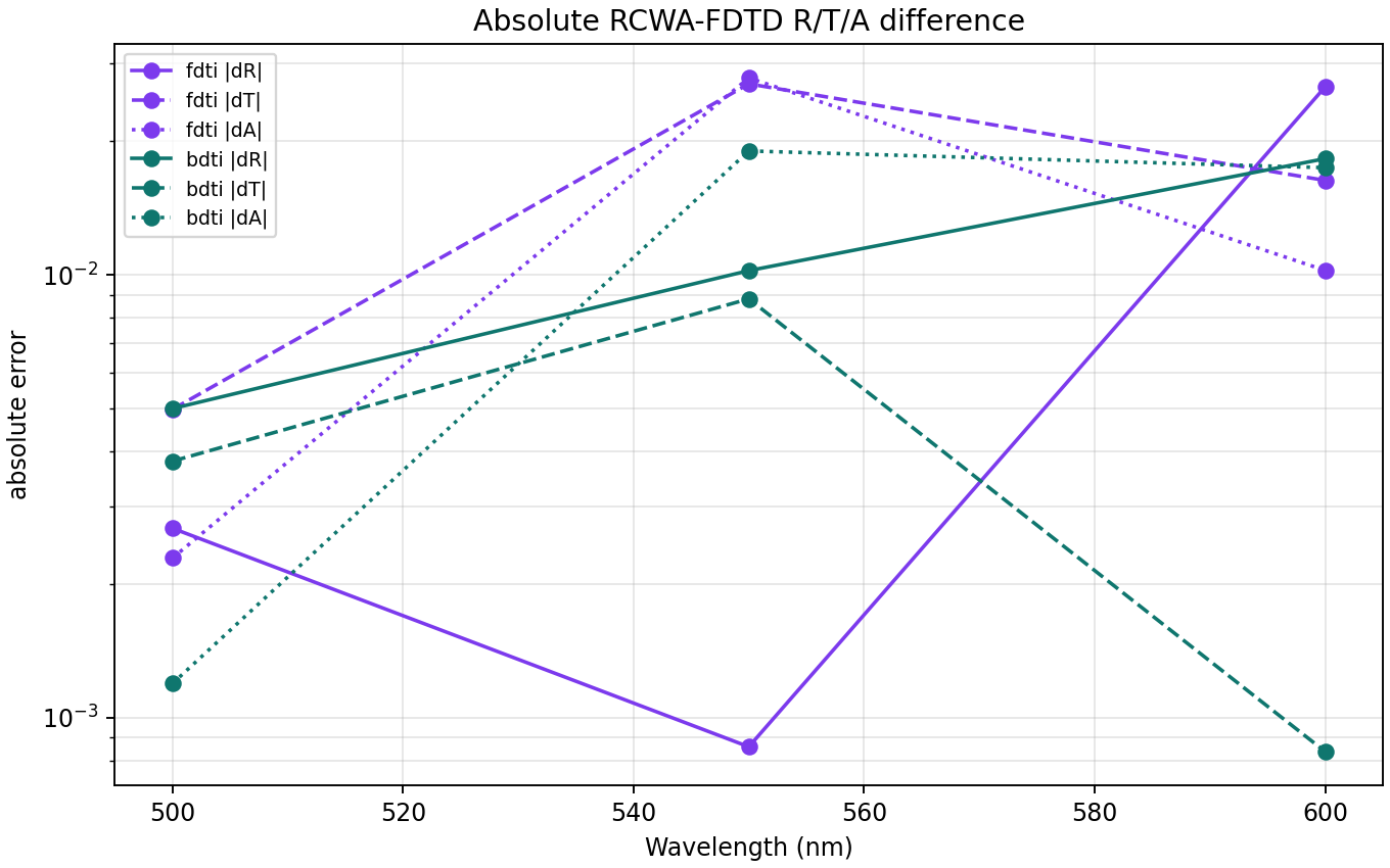
03 Rta Error
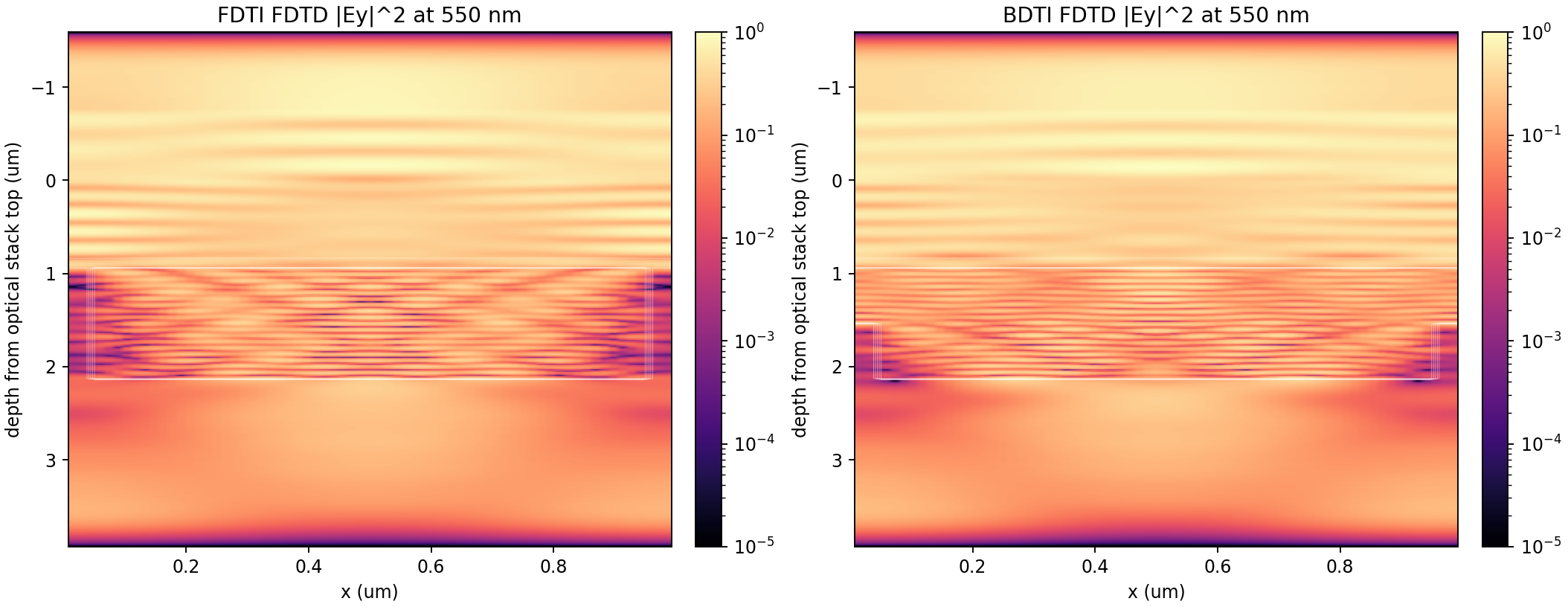
04 Fdtd Field Maps
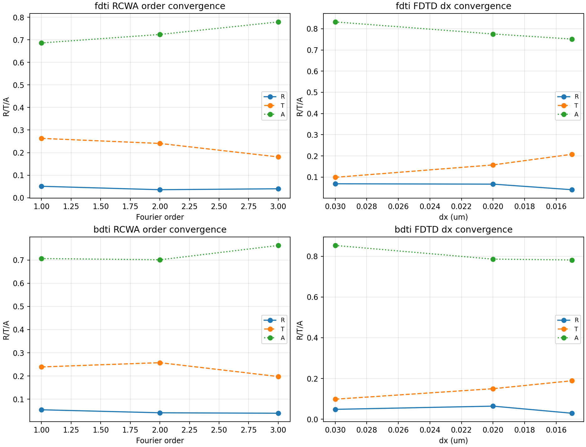
05 Convergence
Full 2x2 Bayer pixel convergence
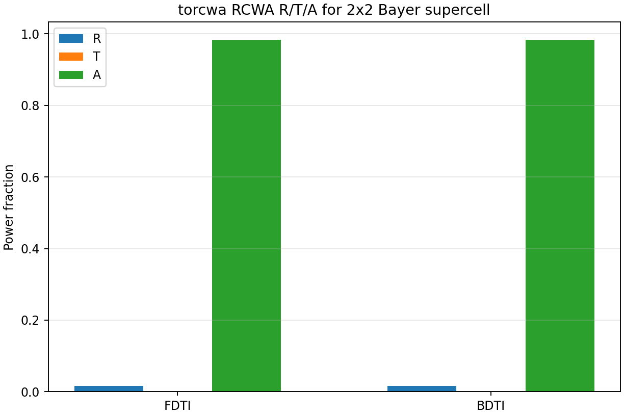
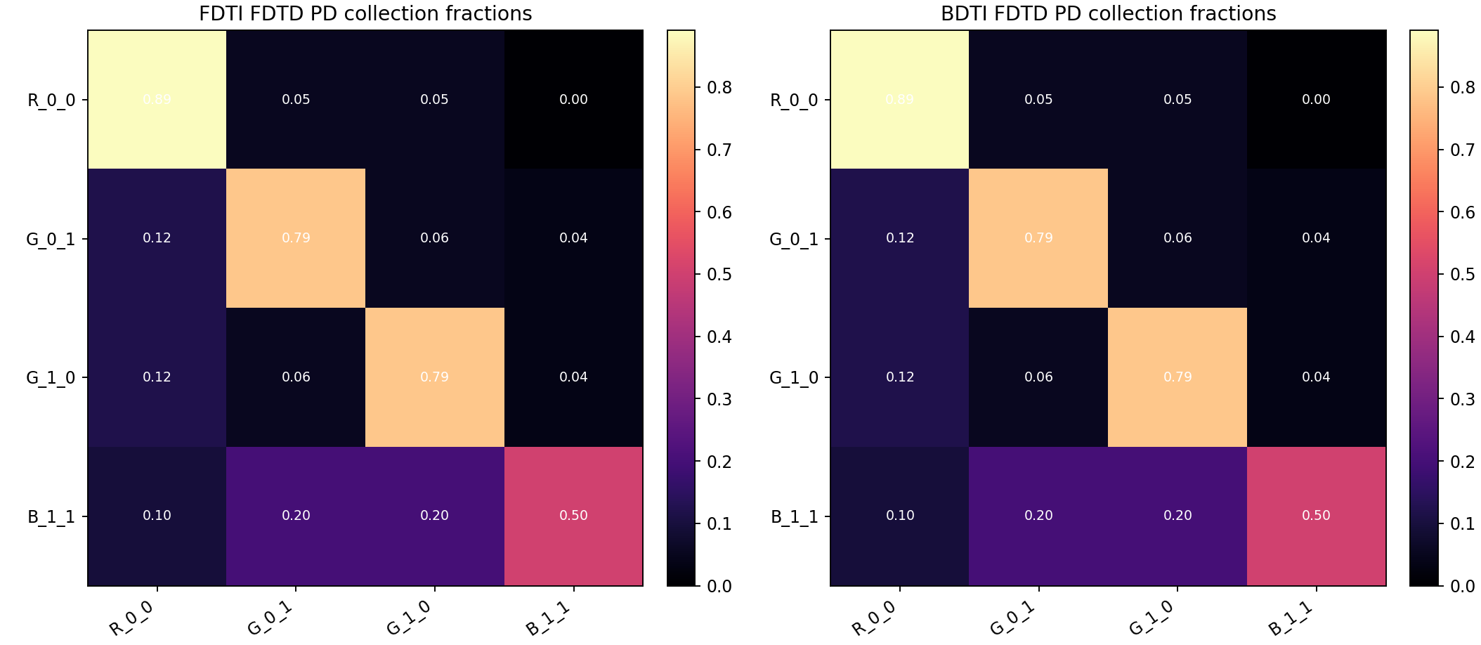
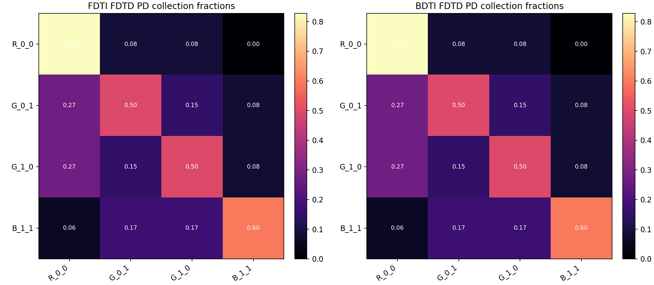
The pixel benchmark uses the real PixelStack path with FDTI/BDTI options, material-database complex indices, BARL layers, microlens slices, color filters, and photodiode integration windows. RCWA reports full-supercell R/T/A, while the scalar FDTD path reports localized-source collection and crosstalk proxies.
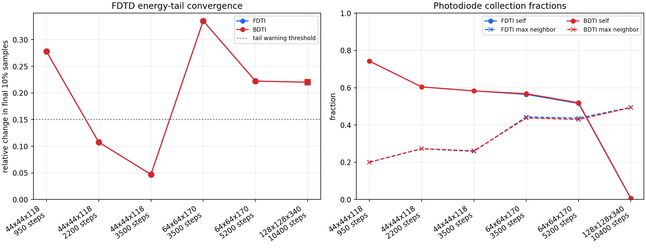
Pixel convergence summary generated from all available pixel benchmark metrics.
| Grid | steps | sources | mode | dx um | c*time um | self frac | max neighbor | tail | warnings |
|---|---|---|---|---|---|---|---|---|---|
| 44x44x118 | 950 | all | FDTI | 0.0455 | 9.5962 | 0.7426 | 0.2003 | 0.278 | 1 |
| 44x44x118 | 950 | all | BDTI | 0.0455 | 9.5962 | 0.7426 | 0.2003 | 0.278 | 1 |
| 44x44x118 | 2200 | all | FDTI | 0.0455 | 22.2228 | 0.6041 | 0.2724 | 0.1077 | 0 |
| 44x44x118 | 2200 | all | BDTI | 0.0455 | 22.2228 | 0.6041 | 0.2728 | 0.1077 | 0 |
| 44x44x118 | 3500 | all | FDTI | 0.0455 | 35.3544 | 0.5831 | 0.2582 | 0.0471 | 0 |
| 44x44x118 | 3500 | all | BDTI | 0.0455 | 35.3544 | 0.5827 | 0.2609 | 0.047 | 0 |
| 64x64x170 | 3500 | all | FDTI | 0.0312 | 24.3794 | 0.5639 | 0.4434 | 0.3352 | 1 |
| 64x64x170 | 3500 | all | BDTI | 0.0312 | 24.3794 | 0.5677 | 0.4377 | 0.3353 | 1 |
| 64x64x170 | 5200 | all | FDTI | 0.0312 | 36.2208 | 0.5155 | 0.4367 | 0.2222 | 1 |
| 64x64x170 | 5200 | all | BDTI | 0.0312 | 36.2208 | 0.5192 | 0.4293 | 0.2223 | 1 |
| 128x128x340 | 10400 | single | FDTI | 0.0156 | 36.2208 | 0.0061 | 0.4945 | 0.22 | 1 |
| 128x128x340 | 10400 | single | BDTI | 0.0156 | 36.2208 | 0.0071 | 0.4933 | 0.2201 | 1 |
Pixel plots
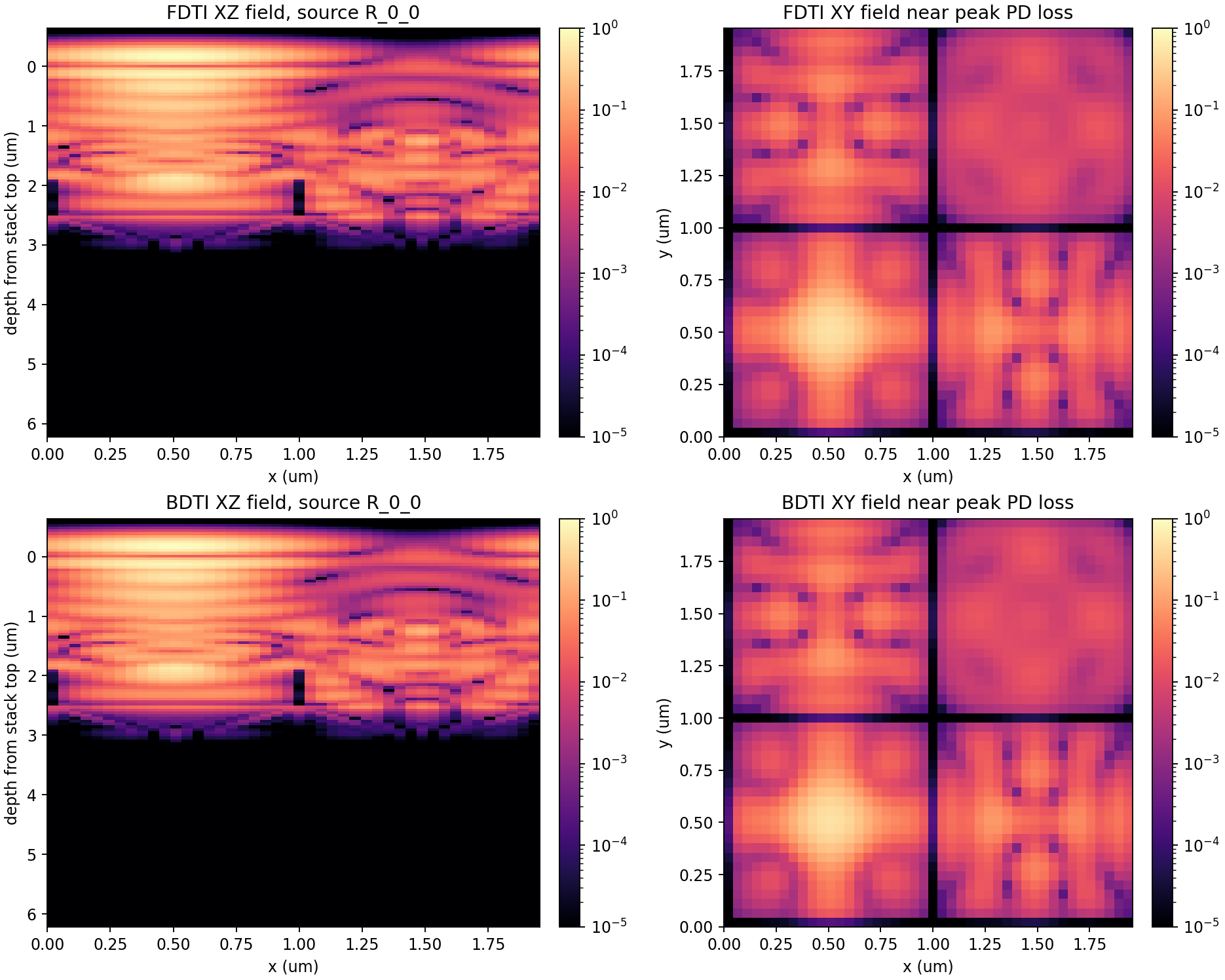
The benchmark folders include geometry and RCWA R/T/A images for every run, but those two plots are intentionally identical because each run uses the same physical 2x2 BSI stack and the same RCWA reference. They are shown once below. The per-run sections show only the FDTD crosstalk matrix and field slices, which change with grid, runtime, and source settings.
Shared geometry and RCWA reference
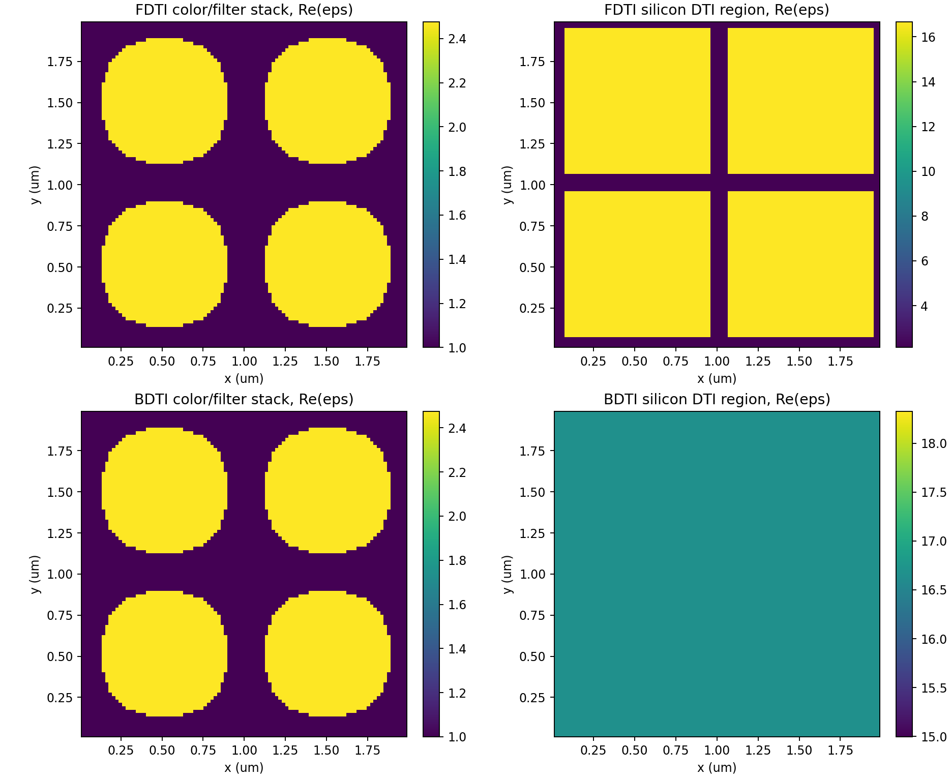
01 Geometry Slices
02 Rcwa Rta
2x2 pixel scalar FDTD, 44x44x118, 950 steps
03 Fdtd Crosstalk Matrix
04 Fdtd Field Slices
2x2 pixel scalar FDTD, 44x44x118, 2200 steps
03 Fdtd Crosstalk Matrix
04 Fdtd Field Slices
2x2 pixel scalar FDTD, 44x44x118, 3500 steps
03 Fdtd Crosstalk Matrix
04 Fdtd Field Slices
2x2 pixel scalar FDTD, 64x64x170, 3500 steps
03 Fdtd Crosstalk Matrix
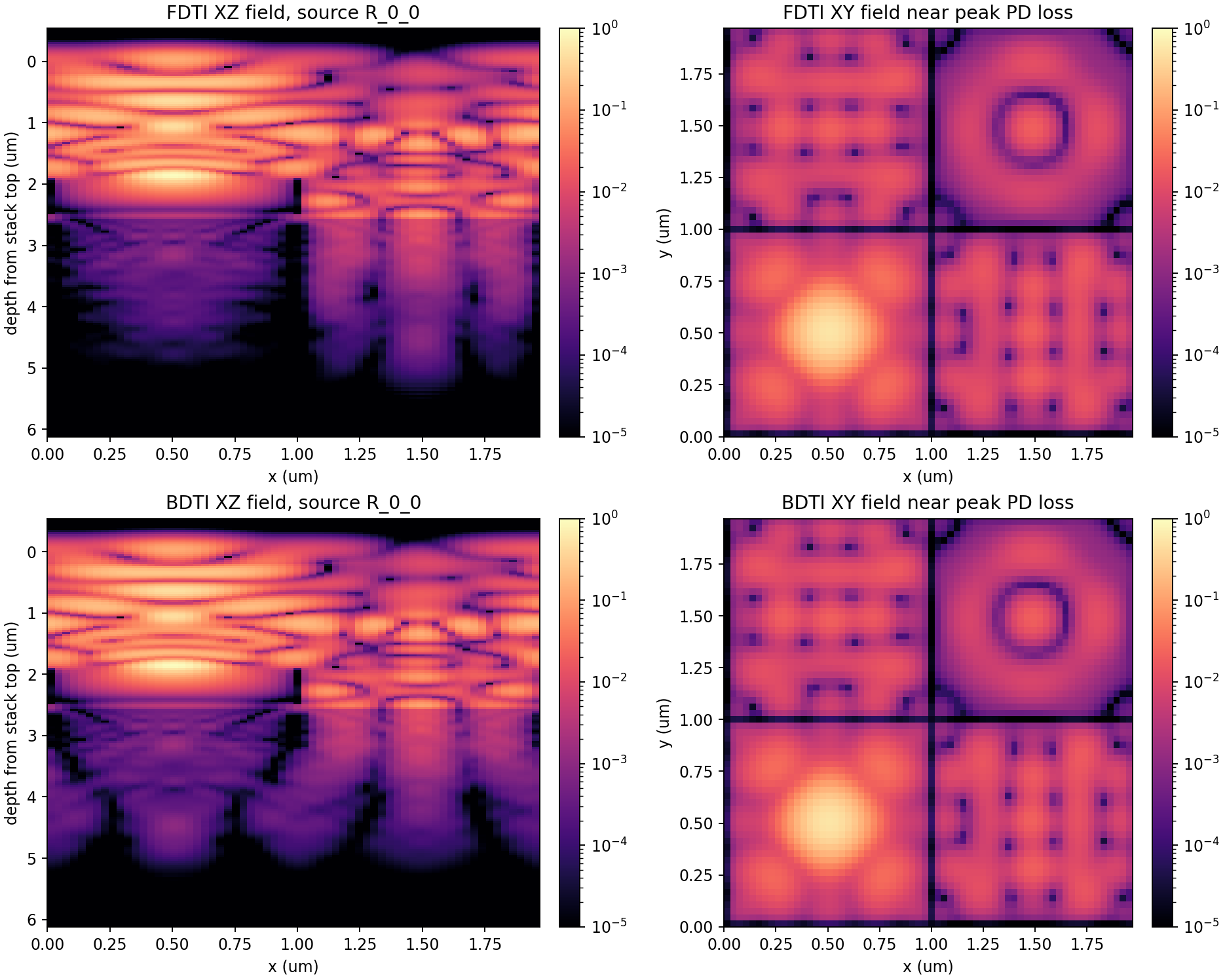
04 Fdtd Field Slices
2x2 pixel scalar FDTD, 64x64x170, 5200 steps
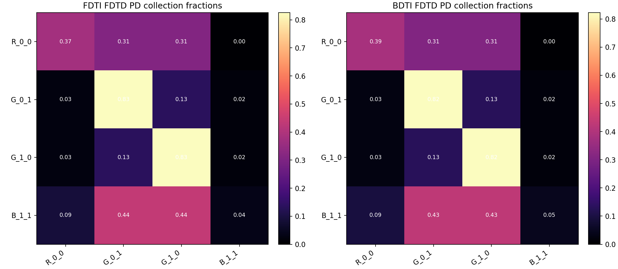
03 Fdtd Crosstalk Matrix
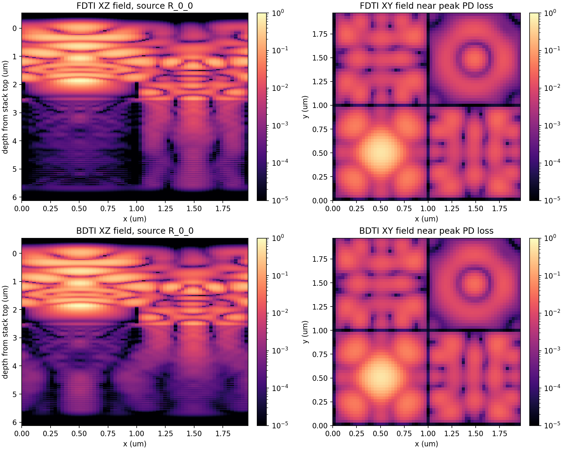
04 Fdtd Field Slices
2x2 pixel scalar FDTD, 128x128x340, single source, 10400 steps
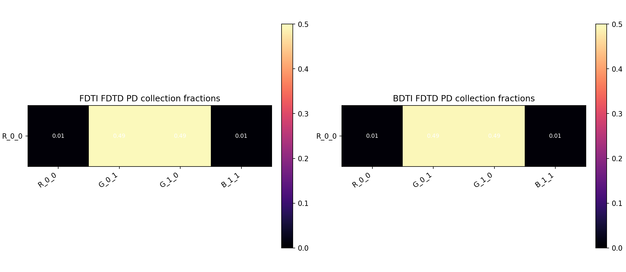
03 Fdtd Crosstalk Matrix
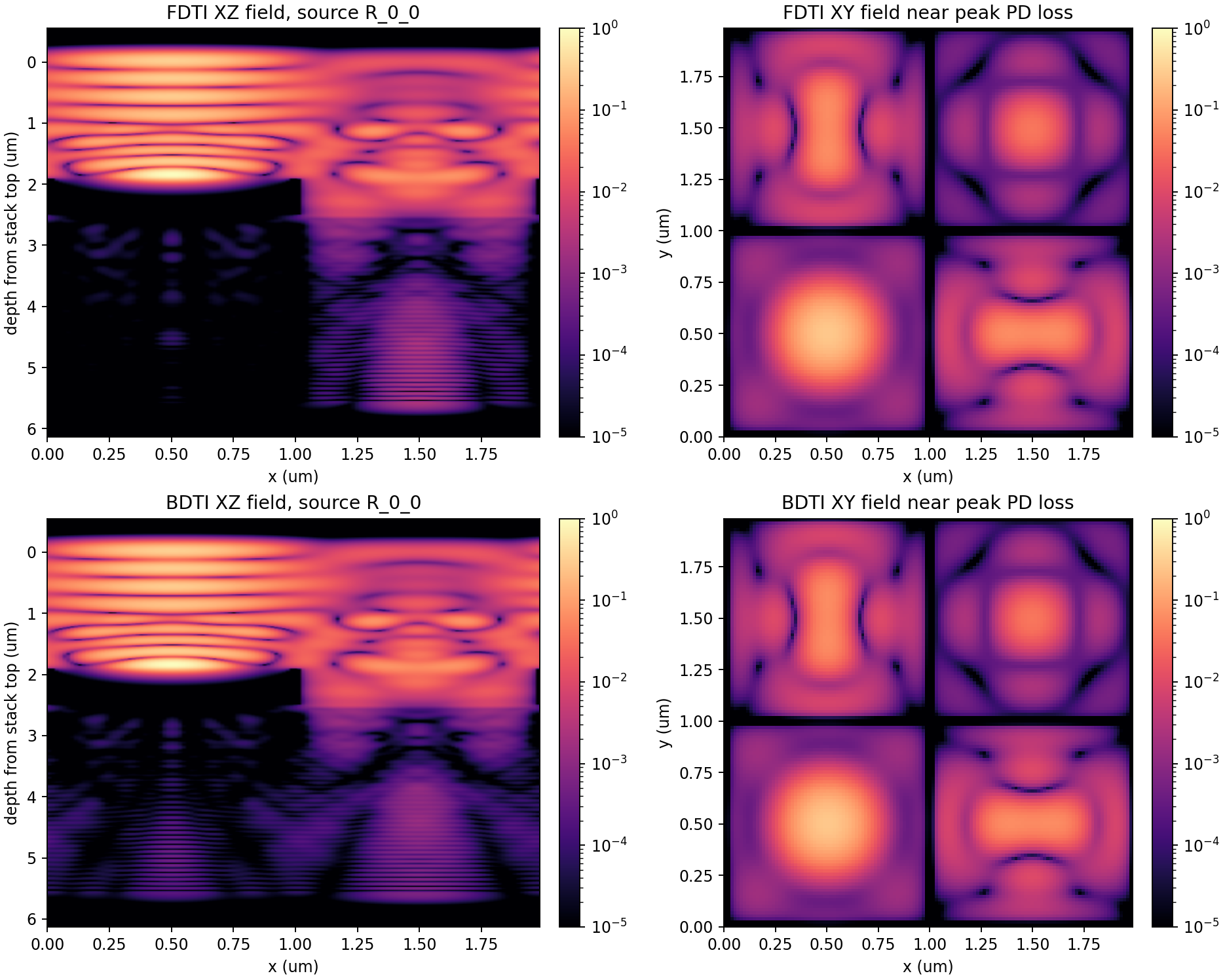
04 Fdtd Field Slices
Visual smoke-test artifacts
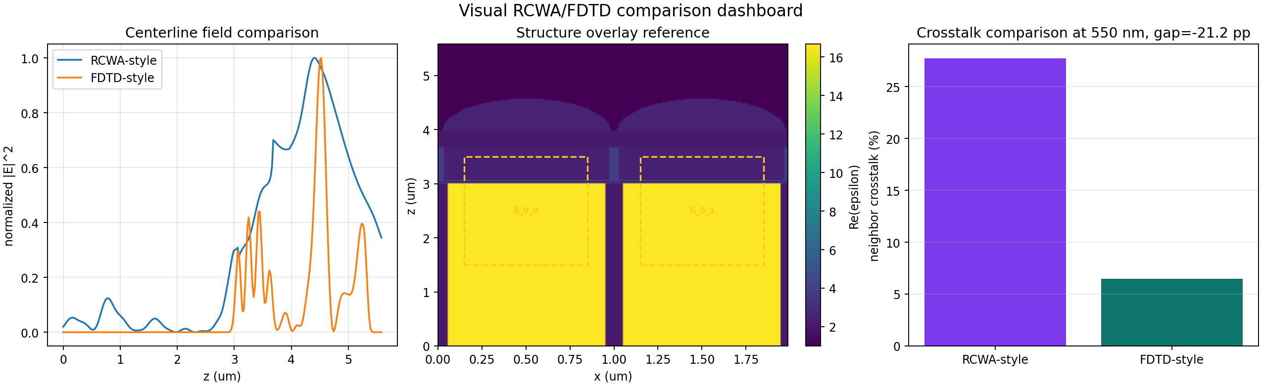
These plots are not used as rigorous solver evidence. They are retained as fast visual tests for the FDTI/BDTI geometry, photodiode windows, and plotting pipeline.
Visual CMOS pixel smoke test
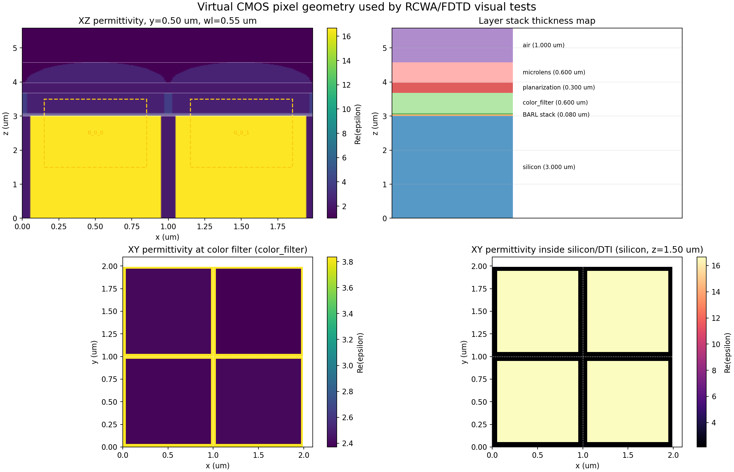
01 Geometry Overview
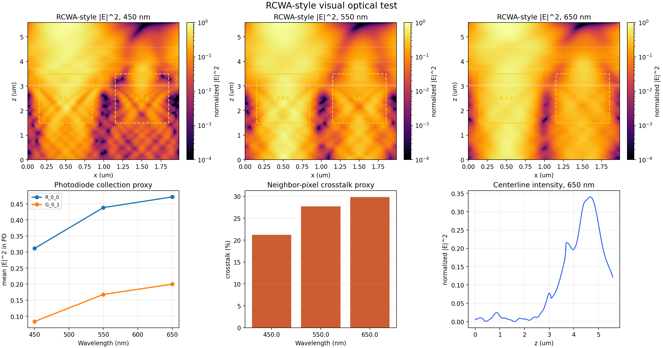
02 Rcwa Visual Test
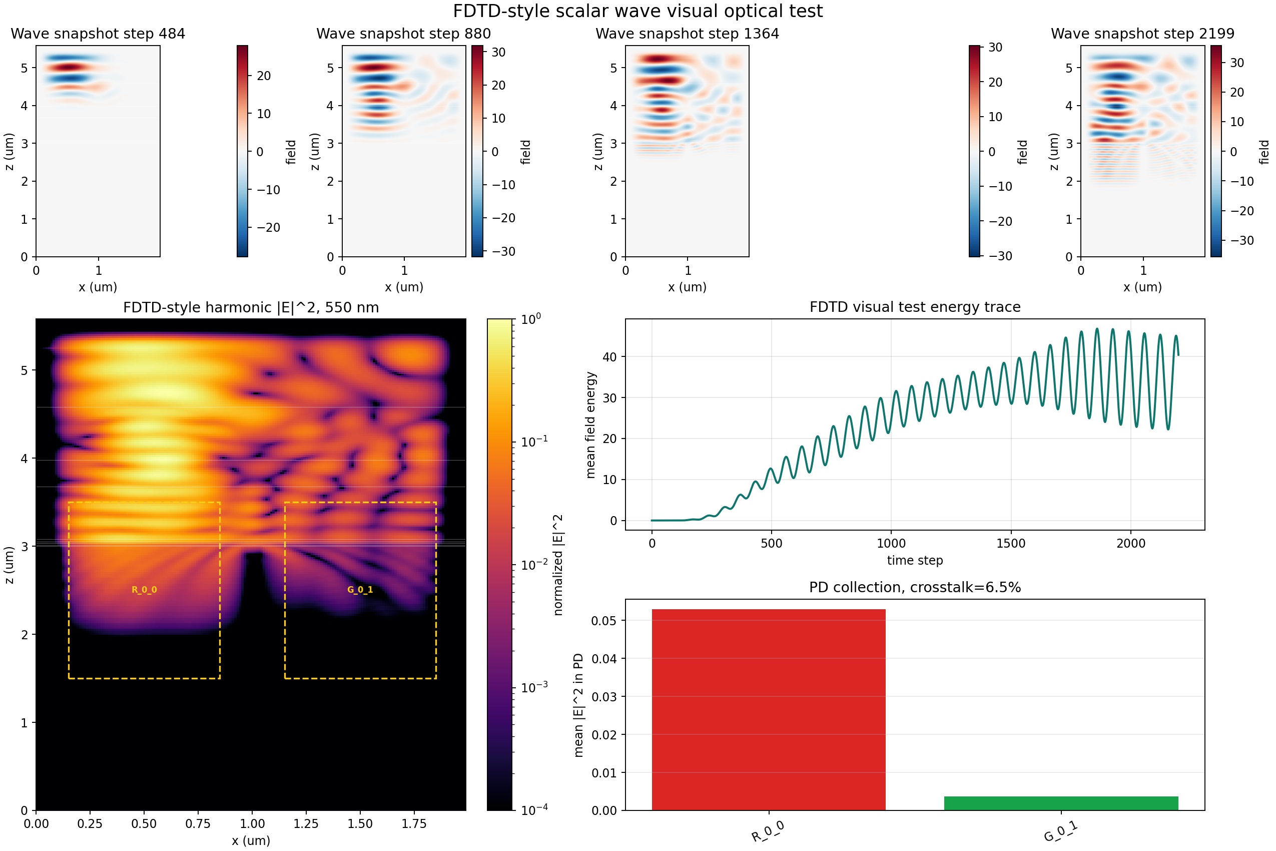
03 Fdtd Visual Test
04 Rcwa Fdtd Comparison
How to act on this report
For users
- Use the 44x44x118, 3500-step pixel rows as the current stable visual comparison point for FDTI/BDTI behavior.
- Treat the 64x64x170 and 128x128x340 rows as diagnostic evidence, not final performance claims, because their physical runtime is still short.
- Prefer the convergence-study cookbook page for routine parameter choices; use this report when you need the evidence behind those choices.
For maintainers
- Use the 1D ladder to validate normalization, material loss, and monitor math before debugging full pixels.
- Use the periodic trench benchmark to compare FDTI and BDTI with the same geometry, boundary conditions, and R/T/A definitions.
- For final high-accuracy work, scale FDTD steps with grid refinement, run all four sources, and repeat the RCWA side with Fourier order and permittivity-grid sweeps.