- ”.
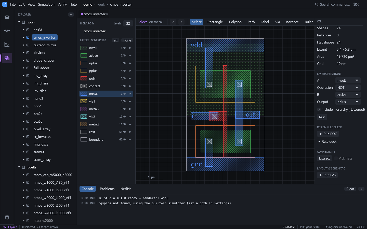
- Left panel: Hierarchy (drawn levels and the tree of placed cells), Layers,
and the options of the current tool.
- Toolbar: undo / redo, the tools (Select, Stretch, Move, Copy, Rectangle,
Polygon, Path, Label, Via, Instance, Chop, Ruler), fit,
Zoom box, Prev view, Grid, Snap, Gravity, DRD, Constraints,
Magnet, Live DRC, Flylines, and GDS to export the cell.
- Status bar:
X / Y of the cursor; while a command is in progress dX, dY and
Dist from its reference point; Sel: n (Sel(P): n for a partial selection); Cmd:
the current tool; and a mouse L: … M: … R: … line telling what each button does now.
- Right panel: cell statistics or the inspector, Edit operations, Layer
operations, and the verification sections (see Verification).
- Click a layer row to make it the active layer; new shapes are drawn on it.
- Click the eye to show or hide a layer. Click the small box left of the eye to make a
layer selectable or not: shapes on non-selectable (or hidden) layers are drawn but
cannot be picked, like Virtuoso’s LSW. AV / NV show / hide every layer, AS /
NS make every layer selectable / not.
- Filter narrows the list by name; Instances selectable controls whether placed
cells can be picked.
- Each row shows the fill pattern, the name and the GDS
layer/datatype. Hover a row to
see its minimum width and spacing.
Keys act on the canvas only while the mouse is over it.
| Tool | Key | How to use |
|---|
| Select | Esc | Click, Shift/Ctrl+click, or drag a box |
| Stretch | S | Click an edge or vertex of a shape, then the destination (or drag it). Or drag a box away from any edge: the vertices inside become the partial selection; then click a reference point and the destination |
| Rectangle | R | Drag from corner to corner, or click two corners; the size is shown |
| Polygon | Shift+P | Click each vertex; Enter, double-click or right-click closes it |
| Path | P | Click points; Enter, double-click or right-click finishes it |
| Label | L | Type the Text in the left panel, click to place |
| Via | O | Pick a via in the left panel; click for one cut, drag to fill an area |
| Instance | I | Pick a cell or PCell in the left panel, click to place |
| Chop | Shift+C | Drag or click a box; it is cut out of the selected shapes (or of every selectable shape it touches) |
| Ruler | K | Drag or click two points; rulers stay until Shift+K |
While drawing a polygon or path, Backspace removes the last point and Esc cancels.
-
Gravity (on by default, G toggles) snaps the cursor to vertices (diamond marker) and edges
(circle marker) of nearby shapes and instance boxes, so new geometry abuts exactly.
-
DRD (design-rule-driven editing, on by default) shows the minimum-spacing halo of a
rectangle being drawn and marks in red every gap to a same-layer shape that is closer
than the minimum spacing, and shapes narrower than the minimum width. It works while
drawing rectangles and paths, moving, copying and pasting. Neighbours inside placed cells
count too (at any depth), as do the shapes around a cell edited in place; a moved or
pasted instance is checked by the shapes along its outline.
-
Magnet (on by default) pulls a shape being drawn or moved to exactly the minimum
spacing from its neighbours when it comes close.
-
Live DRC (on by default) checks the rule deck around every edit; see
Live DRC.
-
Layer tap: T makes the layer of the shape under the cursor the active layer.
-
Changing metal while routing: with the Path tool, press + (or = / PageUp) to
end the path at the cursor, drop the via to the routing layer above and continue on it;
- (or PageDown) goes down.
-
Polygons are Manhattan by default: each point is aligned horizontally or vertically
to the previous one. Hold Shift (or Ctrl) while clicking for any angle. The closing
edge gets an extra corner so a Manhattan outline stays Manhattan.
-
Paths are always Manhattan. Width (nm) in the left panel sets the width; 0
uses the layer’s minimum width. Path ends are extended by half the width.
-
Labels on a routing layer name the net under them (used by extraction and LVS).
-
Vias come from the technology (bottom layer, cut, top layer); dragging an area
fills it with as many cuts as fit.
- Click the
metal1 row in Layers.
- Press
R and drag on the canvas.
- Press
Esc to return to Select, click the rectangle and type exact
coordinates in the inspector (x0, y0, x1, y1 in µm).
| Action | How |
|---|
| Select | Click; the smallest shape under the cursor wins. Click the same spot again to cycle through the items under it |
| Add / remove | Shift+click or Ctrl+click |
| Box select | Drag on empty space: left to right selects items fully inside, right to left (dashed box) every item it touches; Shift adds |
| Select all | Ctrl+A |
| Move | Drag a selected item; or M, click a reference point, click the destination; or nudge with Shift+arrow keys (10 snap steps). Right-click while moving rotates 90°, Shift+right-click flips sideways |
| Copy | C, click a reference point, then click destinations (each click places another copy, Esc ends); rotate / flip as for Move |
| Stretch | S, click an edge or vertex, click the destination; with a partial selection, click a reference point, then the destination; or drag a box over several edges (see below) |
| Yank / paste | y or Ctrl+C copies the selection (Ctrl+X cuts it); Shift+Y or Ctrl+V attaches it to the cursor, click to place. The clipboard also works between cells |
| Merge / chop | Shift+M / Shift+C |
| Reshape | With one shape selected, drag a vertex handle (square) or an edge handle (round); Manhattan shapes stay Manhattan |
| Rotate 90° / flip | Shift+O, or Rotate 90°, Flip X, Flip Y |
| Deselect all | Ctrl+D |
| Delete | Del or Backspace |
| Undo / redo | u / Shift+U, or Ctrl+Z / Ctrl+Shift+Z or Ctrl+Y |
| Descend | Shift+X over an instance (or with one selected) opens its cell on its own; Shift+B returns. Shift+T shows the hierarchy tree |
| Flip | Ctrl+J flips the selection sideways, or what is being moved or copied |
| Edit in place | x over an instance (or with one selected) edits its cell, or the array element under the cursor, inside the parent: the surroundings stay visible, dimmed, in the parent’s orientation, and DRD checks against them. Shift+B or Return in the toolbar goes back |
| Open a placed cell | Double-click the instance, or Open in the inspector |
| Pop-up menu | Middle-click, or right-click when no command point is pending: Move, Copy, Stretch, Delete, Properties, Rotate 90°, Merge, Yank, Paste, Descend Edit, Return, Fit All, Previous View, plus Edit In Place. With nothing selected, the item under the cursor is selected first |
F4 (or Edit > Toggle Partial Select) toggles partial selection. In Select, a click
near an edge selects that edge (both its vertices) or a vertex; Shift+click adds or
removes; a drag box selects the vertices inside it (items entirely inside are taken whole).
Selected edges and vertices are highlighted and the status bar shows Sel(P): n.
Press S, click a reference point, then the destination: every selected vertex moves, and
Manhattan shapes stay Manhattan (adjacent edges slide along). Dragging a partially selected
shape in Select stretches it too. Esc clears the partial selection.
Each key opens a floating form and closes it again:
| Key | Form |
|---|
q | Edit Object Properties: the inspector for the selection |
F3 | Options of the current command (path width, label text, via, instance placement; snap and gravity for commands without options) |
e | Display Options: grid, display levels From 0 To N, flylines, clear rulers |
Shift+E | Layout Editor Options: snap spacing, gravity, DRD, instances selectable, partial selection, default path width |
The Edit section of the right panel (shown when something is selected) also has:
- Flatten: replace the selected instances with their contents (one level).
- Make cell: move the selection into a new cell and place an instance of it.
- Merge: union the selected shapes per layer.
- Size with Apply: grow (positive µm) or shrink (negative) the selected shapes.
- Align (two or more items): align left, centre or right edges, bottom, centre or top
edges; Space X / Space Y spread three or more items with equal gaps.
| Action | How |
|---|
| Zoom | Ctrl+wheel or pinch, [ in / ] out at the cursor, Shift+Z out (Conventional profile: the wheel) |
| Zoom box | Right drag, or Z (or Zoom box), then drag or click two corners |
| Previous / next view | W / Shift+W (or Prev view) |
| Fit | F |
| Pan | Wheel (up / down), Shift+wheel (sideways), middle drag, or the arrow keys |
| Pop-up menu | Middle-click (or right-click when no command point is pending) |
These are the Virtuoso interaction profile, the default. With Conventional
(Settings > Interaction) the wheel zooms and a right drag pans.
Bindkeys go to the canvas while the mouse is over it, and stay with it while one of its
forms (q, F3, e, Shift+E) is open on top, until you click elsewhere in the window.
A text field being typed in, or a focused control in a form under the mouse, gets the keys
first.
With nothing selected, Layer operations computes Boolean results:
- Choose layer A, an Operation (AND, OR, NOT, XOR, SIZE) and layer B (or a
distance By in µm for SIZE).
- Choose the Output layer.
- Keep Include hierarchy (flattened) checked to include placed cells.
- Press Run. The result shapes are added to the output layer and selected.
Boolean operations, Merge, Size and Chop handle any-angle geometry (45° and
arbitrary edges, from GDS / OASIS or the polygon tool) exactly. Crossings that fall between
grid points snap to the nearest database unit. When sizing, horizontal, vertical and 45° edges
move by the given distance and corners of 90° or more stay sharp. Results with holes are cut
into hole-free polygons.
These commands have no menu or bindkey; run them from the command palette, where they are
listed as “Layout Assist: - ”.
- Symmetric About Vertical / Horizontal Axis, Keep Left / Bottom Edges Aligned,
Keep Centres Aligned Vertically / Horizontally and Fix In Place add a constraint
to the selected items. Moving one member moves the others so the constraint keeps holding.
Infer Constraints From Schematic adds symmetry constraints for the schematic’s
matched devices; Remove Constraints clears them. The Constraints checkbox in the
toolbar draws them, and the Constraints section of the right panel lists them, with
Snap for one that no longer holds.
- Compact (Left, Then Down) and Compact Left / Right / Down / Up slide the cell’s
top-level items toward one side as far as the spacing rules allow. Connected geometry and
the members of a constraint move together.
- Compare With Saved and Compare With Git HEAD draw the geometry added and removed
since the last save or the last commit; Next Difference steps through them.
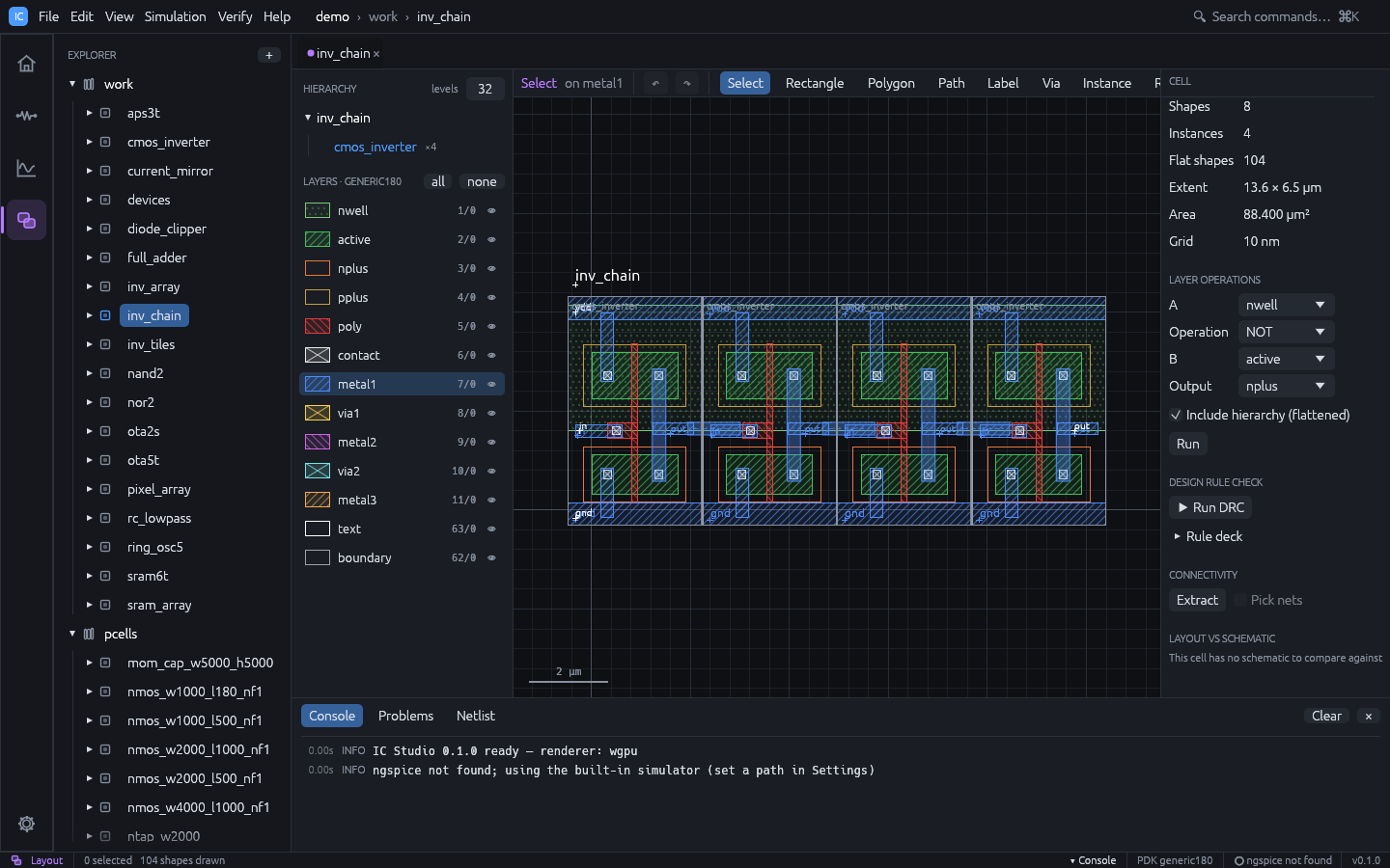
- Press
I. The left panel lists PCell variants and Place cell (every other
cell with a layout that would not create a cycle).
- Pick a cell, set Rotation, Mirror about x, Columns and Rows. Array
elements abut at the cell’s extent.
- Click to place.
Select an instance to edit its position, rotation and mirroring in the inspector. Check
Array to turn it into an array (GDS AREF) with Columns, Rows, Column pitch
and Row pitch.
The levels field in Hierarchy (keys 0 to 8, and 9 for all levels) sets how
many levels of placed cells are drawn with their contents (Shift+F all levels, Ctrl+F
top level only). Deeper instances are drawn as
labelled boxes. Missing cells are drawn in red.
Large designs stay fast: cells that are small on screen collapse to boxes and tiny shapes
to dots.
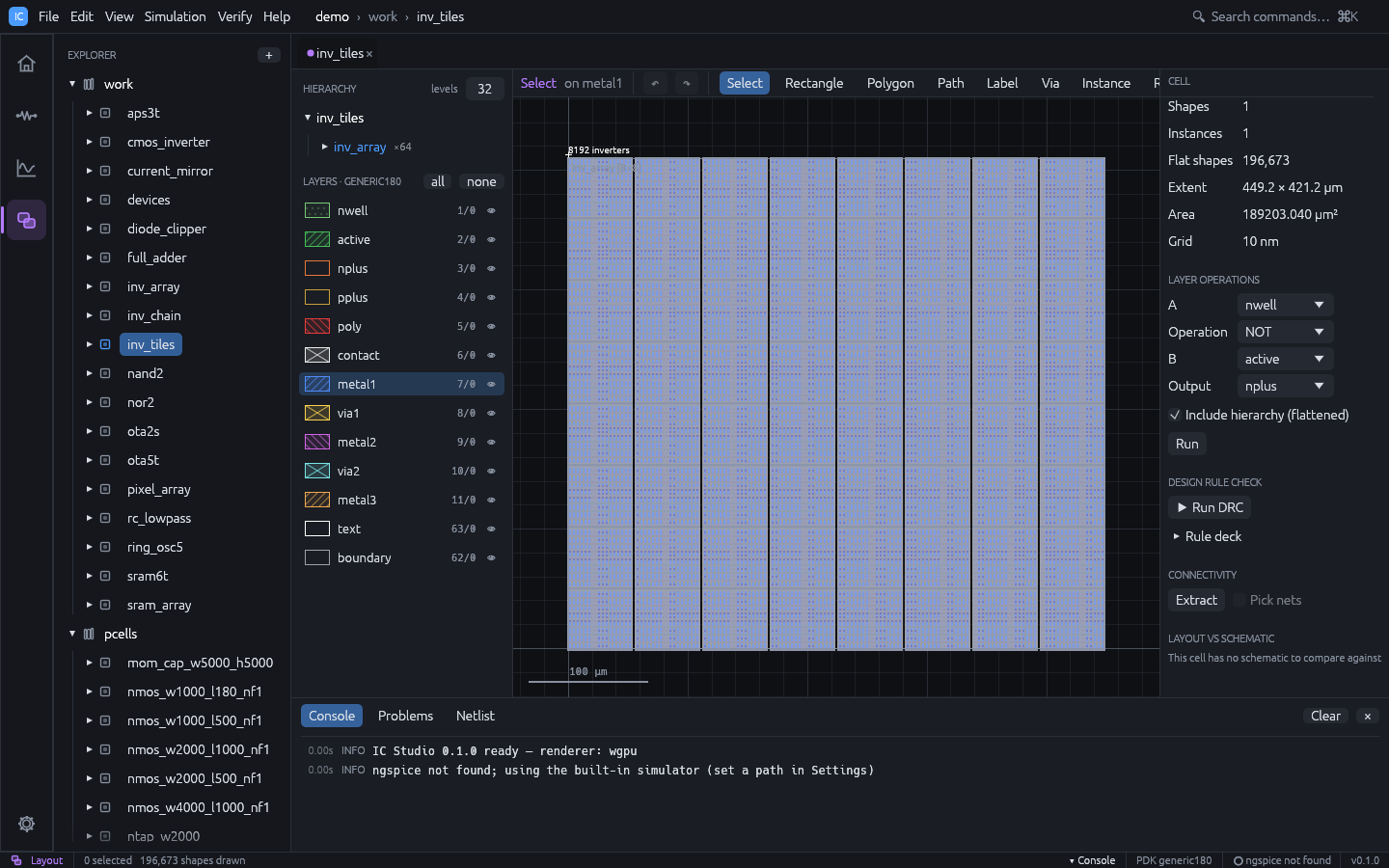
The hierarchy tree (Edit > Hierarchy Tree, Shift+T) lists the cells placed in the
current cell with their counts; click one to open it. Tools > Hierarchy Browser shows
the whole project’s layout hierarchy with where-used lists (see
Tools).
The Tools menu also adds geometry to the active layout, each as one undoable step:
- Layout Generators > Guard Ring: a p+ substrate or n+ nwell ring with contacts and a
metal1 strap around an area or the selection;
- Layout Generators > Via Array: via arrays on every overlap of two layers, or filling
an area;
- Layout Generators > Matched Placement: common-centroid, interdigitated or 2-D
common-centroid placement of matched transistors with dummies;
- Layout Generators > By Example: place the devices like a finished cell with the same
circuit (matched by topology), copying its wells, implants and taps, and optionally route;
- Dummy Fill: fill squares to meet a density rule.
See Tools for the options.
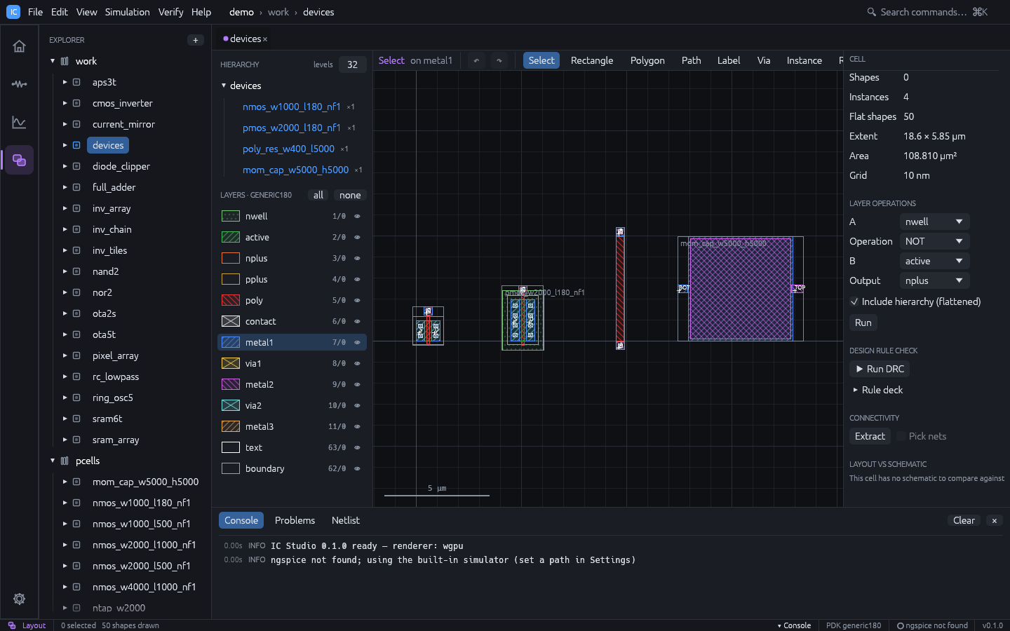
Parametric cells are generated from the technology and stored as ordinary cells in the
pcells library (for example nmos_w1000_l180_nf2).
| PCell | Parameters | Defaults |
|---|
nmos | W, L, fingers, device | W 1 µm, L 0.18 µm, 1 finger |
pmos | W, L, fingers, device | W 2 µm, L 0.18 µm, 1 finger |
poly_res | W, L | W 0.4 µm, L 5 µm |
mom_cap | W, H | 5 µm x 5 µm |
Device appears when the technology is a PDK with several MOS devices of that polarity
(for example low- and high-Vt variants): the PCell then draws that device’s marker layers,
and the variant name ends with the device name. The default is the PDK’s first device.
To place one, press I, choose the PCell in the left panel, set its parameters and click.
To change a placed PCell, select it, edit the parameters in the PCell section of the
inspector and press Apply. Well and substrate taps (ntap, ptap) are created by
schematic-driven layout; their parameters can be edited in
the inspector the same way.
Tools > Load SKILL (.il) runs a Cadence SKILL file on the project; ics skill and
the MCP tool run_skill do the same from the command line and from agents. Printed output
goes to the log, every changed layout can be undone, and geGetEditCellView() returns the
cell open in the editor.
The CIW tab of the bottom panel (Tools > SKILL CIW, or “CIW” in the command palette) is
an interactive SKILL prompt like Virtuoso’s Command Interpreter Window. Variables,
procedures and open cellviews persist between commands and include everything defined by
files loaded with Tools > Load SKILL; opening another project starts a fresh
session. Enter runs the line, a line with unclosed parentheses or strings continues on the
next one (the prompt shows ...), and Up / Down recall earlier commands.
cv = dbOpenCellViewByType("work" "pad" "layout" "maskLayout" "w")
for(i 0 3
  dbCreateRect(cv list("metal1" "drawing") list(i*2:0 i*2+1:1)))
dbCreateInstByMasterName(cv "work" "via_cell" "layout" "I0" 0:5 "R90")
printf("%d shapes\n" length(cv~>shapes))
Supported:
- syntax: C style
f(a b) and Lisp (f a b) calls, infix operators, x:y points,
obj~>prop, tbl[key], 'quote, ?key arguments, ; and /* */ comments, scale
factors such as 1.5u;
- control:
if / then / else, when, unless, cond, case, while, for,
foreach (also mapcar and tables), let, prog / return, setof, exists,
errset, error;
procedure / defun with @optional, @key, @rest, lambda, funcall, apply,
mapcar, load; list, string, math and printf / sprintf built-ins, makeTable tables
and disembodied property lists;- layout:
dbOpenCellViewByType ("r", "w" clears the layout, "a" appends; libraries and
cells are created on demand), dbCreateRect, dbCreatePolygon, dbCreatePath,
dbCreateLabel, dbCreateInst, dbCreateInstByMasterName, dbCreateSimpleMosaic,
dbDeleteObject, dbMoveFig, dbCopyFig, dbFindAnyInstByName, dbGetOverlaps,
dbTransformPoint / dbTransformBBox; layer Boolean operations dbLayerAnd, dbLayerOr,
dbLayerXor, dbLayerAndNot (cv layer shapes1 shapes2) and dbLayerSize
(cv layer shapes size), which add the result to layer and return the new shapes (any-angle
geometry included); dbSave and dbClose do nothing (save the project).
Shape, instance and cellview properties (bBox, points, layerName, xy, orient,
shapes, instances, …) can be read, and the geometric ones set.
Coordinates are in µm. A layer is a name, list(name purpose) or a layer index; a purpose
other than drawing first looks for a layer named name.purpose or name_purpose.
Variables are dynamically scoped as in .il files. Not supported: schematic views, PCell
definitions (pcDefinePCell), interactive hi* / le* forms and SKILL++ (.ils) lexical
scoping.
- File > Import > GDSII / OASIS… reads a GDS or OASIS file into a new library with full hierarchy.
- GDS in the toolbar or File > Export > Cell GDSII… writes the cell and every
cell it places; Export > Library GDSII… writes every layout in the project.
Cell OASIS… and Library OASIS… write OASIS instead.
Layers are mapped by GDS layer / datatype. Layers the technology does not have are added
to it on import, so nothing is lost. A stream layer map
(Tools > Stream Layer Map, or a Virtuoso layer map file) renumbers layers on export,
maps other numbers onto technology layers on import, or drops them.